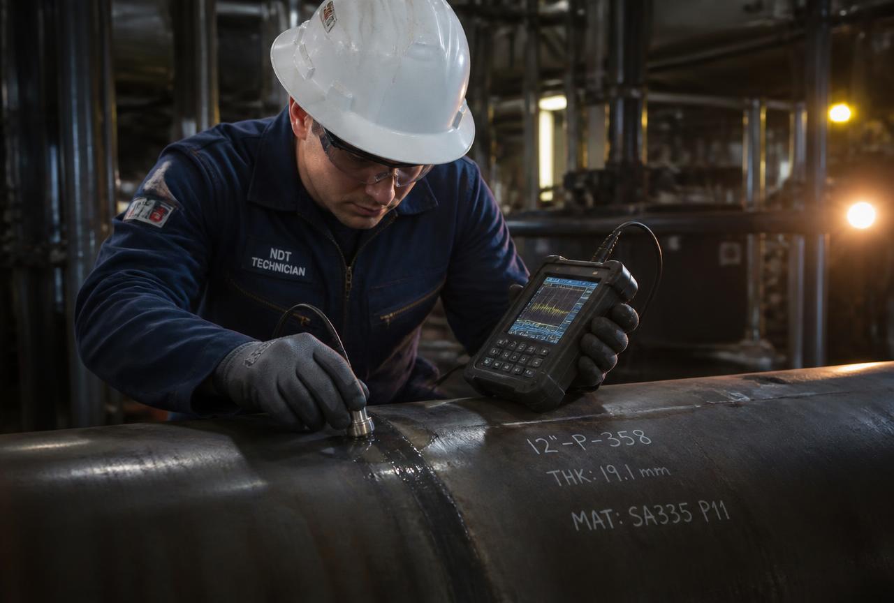
Technician performing ultrasonic testing on an industrial pipe weld

Services

Conventional NDT

UT, RT, MT, PT and VT applied to welds, piping, vessels, tanks and structural components — executed to approved procedures and applicable client specifications.

Request a Quote

Method Overview

Five Core Conventional Methods

Method selection depends on material, geometry, access, the defect types of concern and the governing code or specification.

UT

Ultrasonic Testing

Volumetric examination using high-frequency sound to detect internal discontinuities and to measure remaining wall thickness.

Working Principle
A transducer introduces ultrasonic energy into the component. Reflections from interfaces and discontinuities are timed and amplitude-assessed to locate and size indications.
Typical Indications
  • Lack of fusion
  • Internal cracks
  • Slag inclusions
  • Laminations
  • Wall loss / thinning
Applications
  • Weld examination on piping and vessels
  • Thickness surveys on pipework and tanks
  • Plate and forging inspection
  • Corrosion monitoring locations
Equipment
Portable digital flaw detectors and thickness gauges with appropriate probes and calibration blocks.
Reporting
Indication location, sizing data and thickness readings recorded against the applicable acceptance criteria.
Request a Quote
RT

Radiographic Testing

Volumetric examination producing a permanent radiographic record of the internal condition of a weld or component.

Working Principle
Penetrating radiation passes through the component onto film or a digital detector. Variations in density and thickness appear as contrast differences on the resulting image.
Typical Indications
  • Porosity
  • Slag inclusions
  • Incomplete penetration
  • Cracks
  • Undercut
Applications
  • Butt weld examination on pipe and plate
  • Casting and fabrication inspection
  • Fabrication shop and site scopes
Equipment
Radiographic sources and imaging media suitable for the material and thickness range.
Reporting
Radiographic interpretation reports with technique details and film or image identification.

Radiographic operations are subject to radiation safety requirements, site permits and regulatory authorisation where applicable.

Request a Quote
MT

Magnetic Particle Testing

Surface and near-surface examination of ferromagnetic materials for cracks and linear discontinuities.

Working Principle
The component is magnetised and ferrous particles applied. Flux leakage at a discontinuity attracts the particles, forming a visible indication.
Typical Indications
  • Surface cracks
  • Near-surface cracks
  • Laps and seams
  • Weld toe cracking
Applications
  • Weld surface examination
  • Structural steel and supports
  • Shafts, hooks and lifting components
  • In-service crack detection
Equipment
Yokes, prods and appropriate wet or dry particle media with contrast background as required.
Reporting
Indication type, length and location documented against the acceptance criteria in use.
Request a Quote
PT

Liquid Penetrant Testing

Surface-breaking discontinuity detection on non-porous metallic and non-metallic materials.

Working Principle
Penetrant is applied and allowed to enter surface-breaking discontinuities. After removal of excess penetrant, developer draws the penetrant back to the surface as a visible indication.
Typical Indications
  • Surface cracks
  • Porosity
  • Laps
  • Leak paths
Applications
  • Stainless steel and non-ferrous welds
  • Machined and fabricated components
  • Root and final pass examination
Equipment
Visible dye or fluorescent penetrant systems with appropriate cleaners and developers.
Reporting
Indications recorded with dwell and development times and applicable acceptance criteria.
Request a Quote
VT

Visual Testing

Direct and remote visual examination of surfaces, welds and general asset condition.

Working Principle
Systematic examination under controlled lighting and access conditions, supported by gauges and remote visual aids where direct access is limited.
Typical Indications
  • Weld profile deviations
  • Undercut and overlap
  • Corrosion and mechanical damage
  • Misalignment
Applications
  • Pre-, in-process and final weld inspection
  • General plant condition surveys
  • Fabrication and assembly checks
Equipment
Weld gauges, measuring equipment, lighting and remote visual aids where required.
Reporting
Findings recorded with location references and supporting photographs where permitted.
Request a Quote

Execution

How a Conventional NDT Scope Runs

  1. 01

    Scope, code and acceptance criteria confirmed

  2. 02

    Procedure and technician certification verified

  3. 03

    Calibration and on-site examination

  4. 04

    Reporting and documentation handover

Need Conventional NDT Coverage?

Send us your drawings, weld register or inspection scope and we will confirm method, personnel and timing.